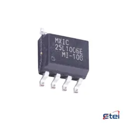
Images are for reference only
74HCT245D
+BOMIC TXRX NON-INVERT 5.5V 20SOIC
-
ManufacturerToshiba Semiconductor and Storage
-
Mfr. Part #74HCT245D
-
Datasheet 74HCT245D DataSheet
-
Package SOIC-14
-
In Stock6073
365 Days Quality Guarantee
7*24 hours service quarantee
90-day after-sales guarantee
Genuine Product Guarantee
Specifications
| Attribute | Value |
| Package | Tape & Reel (TR),Cut Tape (CT) |
| Series | 74HCT |
| ProductStatus | Active |
| LogicType | Transceiver, Non-Inverting |
| NumberofElements | 1 |
| NumberofBitsperElement | 8 |
| OutputType | 3-State |
| Current-OutputHighLow | 6mA, 6mA |
| Voltage-Supply | 4.5V ~ 5.5V |
| OperatingTemperature | -40°C ~ 125°C (TA) |
| MountingType | Surface Mount |
| Package/Case | 20-SOIC (0.295, 7.50mm Width) |
Overview
Description
Key features of the 74HCT245D include an output enable (OE) pin, which controls the tri-state output buffers, and a direction (DIR) pin that determines the data flow direction between the buses (A and B). When OE is low, the bus is enabled, and data can transfer based on the DIR pin's state. The device is known for its fast switching speeds and low power consumption, making it suitable for a variety of applications in computing and communication equipment. It is packaged in various formats including SOIC, TSSOP, and others for flexibility in design.
Equivalent
Features
1. 8-bit Transceiver: It allows for bidirectional data flow between the A and B buses, ideal for buffering and driving data lines.
2. 3-State Outputs: Features 3-state outputs, which can be set to high, low, or high-impedance states, enabling multiple transceivers to connect to the same data lines without interference.
3. TTL-Compatible Inputs: Compatible with TTL logic levels, making it suitable for interfacing with TTL-based systems.
4. High-Speed CMOS Technology: Utilizes advanced CMOS technology for high-speed operation while maintaining low power consumption compared to traditional TTL circuits.
5. Direction Control: Includes a direction control (DIR) input to determine data flow direction between the buses.
6. Enable Control: Features an output enable (OE) input to control the output state, allowing for easy disconnection from the bus.
7. Standard Pin Configuration: Comes in a 20-pin package, facilitating integration into existing designs.
These features make it suitable for applications in computing, networking, and communication systems requiring efficient data buffering and bus interfacing.
Pinout
- Pin Configuration:
- Pins 1 (DIR): Direction control input, determines the data flow direction.
- Pins 2-9 (A1-A8): Data inputs/outputs for the A bus.
- Pins 11-18 (B1-B8): Data inputs/outputs for the B bus.
- Pin 19 (OE): Output enable input, active low; enables the outputs when low.
- Pin 10 (GND): Ground.
- Pin 20 (VCC): Supply voltage.
This IC is typically used in applications requiring bidirectional data buffering and isolation between buses. Its compatibility with TTL levels makes it suitable for use in both TTL and CMOS logic families.