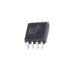
Images are for reference only
74HCT74D
+BOMFlip Flops
-
ManufacturerNexperia
-
Mfr. Part #74HCT74D
-
In Stock8497
365 Days Quality Guarantee
7*24 hours service quarantee
90-day after-sales guarantee
Genuine Product Guarantee
Specifications
| Attribute | Value |
Overview
Description
The 74HCT74D is a dual D-type flip-flop integrated circuit from the 74HCT series. It is designed for use in digital systems requiring high-speed data storage and transfer. Each flip-flop in the chip has independent data (D), clock (CP), set (SD), and reset (RD) inputs, as well as complementary outputs (Q and Q'). The device operates with a supply voltage range of 4.5V to 5.5V, making it compatible with TTL logic levels. The 74HCT74D is known for its fast switching times and low power consumption, making it suitable for various applications in computers, communication equipment, and other electronic systems. Its edge-triggered design ensures that the data is transferred on the rising edge of the clock pulse, providing precise control in synchronous circuits. The chip is typically packaged in small-outline packages (SOP), making it suitable for compact circuit designs. Overall, the 74HCT74D is a versatile component for digital flip-flop applications, offering reliability and efficiency.
Equivalent
The 74HCT74D is a dual D-type flip-flop with set and reset; equivalent products include:
1. SN74HCT74 from Texas Instruments
2. CD74HCT74 from Texas Instruments (formerly from RCA)
3. TC74HCT74A from Toshiba
4. MC74HCT74 from ON Semiconductor (now part of onsemi)
5. 74ACT74 from various manufacturers (though note ACT series is faster)
These equivalents belong to the HCT family, which are high-speed CMOS logic ICs compatible with TTL logic levels. Always check the datasheets for specific electrical characteristics.
1. SN74HCT74 from Texas Instruments
2. CD74HCT74 from Texas Instruments (formerly from RCA)
3. TC74HCT74A from Toshiba
4. MC74HCT74 from ON Semiconductor (now part of onsemi)
5. 74ACT74 from various manufacturers (though note ACT series is faster)
These equivalents belong to the HCT family, which are high-speed CMOS logic ICs compatible with TTL logic levels. Always check the datasheets for specific electrical characteristics.
Features
The 74HCT74D is a dual D-type flip-flop IC with features suitable for a variety of digital applications. Key features include:
1. Logic Family: Belongs to the High-Speed CMOS (HCT) family, compatible with TTL logic levels.
2. Configuration: Contains two independent positive-edge-triggered D-type flip-flops.
3. Inputs and Outputs:
- Each flip-flop has a data (D) input, clock (CP) input, direct set (SD) input, direct reset (RD) input, Q and Q\ (complementary) outputs.
- Asynchronous Set and Reset to initialize or clear outputs regardless of the clock state.
4. Voltage Range: Operates typically at 5V supply voltage, with a range from 4.5V to 5.5V.
5. Propagation Delay: Fast operation with low propagation delay, typically around 16 ns.
6. Power Consumption: Low power consumption due to CMOS technology.
7. Package: Available in various packages like SOIC, TSSOP, and others for versatile hardware integration.
8. Temperature Range: Operates over a wide temperature range suitable for consumer and industrial environments.
These features make it ideal for use in counters, registers, and memory-related digital circuits.
1. Logic Family: Belongs to the High-Speed CMOS (HCT) family, compatible with TTL logic levels.
2. Configuration: Contains two independent positive-edge-triggered D-type flip-flops.
3. Inputs and Outputs:
- Each flip-flop has a data (D) input, clock (CP) input, direct set (SD) input, direct reset (RD) input, Q and Q\ (complementary) outputs.
- Asynchronous Set and Reset to initialize or clear outputs regardless of the clock state.
4. Voltage Range: Operates typically at 5V supply voltage, with a range from 4.5V to 5.5V.
5. Propagation Delay: Fast operation with low propagation delay, typically around 16 ns.
6. Power Consumption: Low power consumption due to CMOS technology.
7. Package: Available in various packages like SOIC, TSSOP, and others for versatile hardware integration.
8. Temperature Range: Operates over a wide temperature range suitable for consumer and industrial environments.
These features make it ideal for use in counters, registers, and memory-related digital circuits.
Pinout
The 74HCT74D is a dual D-type flip-flop IC with a pin count of 14. Each flip-flop within the IC has the following basic functions:
1. Data Input (D): The data on this pin is sampled on the rising edge of the clock.
2. Clock Input (CP): Triggers the flip-flop; on a rising edge, the data from the D input is transferred to the Q outputs.
3. Set (SD)\*: An asynchronous active-low input which, when low, forces the Q output to high, regardless of the clock or data inputs.
4. Reset (RD)\*: An asynchronous active-low input which, when low, forces the Q output to low, regardless of the clock or data inputs.
5. Q Output: The main output of the flip-flop that reflects the current state.
6. Q\* (not Q) Output: The complementary output, which is the inverse of the Q output.
Pins 1 and 2 are for one flip-flop's SD\* and RD\*, respectively, and similar for the second flip-flop at pins 13 and 12. Pin 14 is Vcc, and pin 7 is GND for power supply.
1. Data Input (D): The data on this pin is sampled on the rising edge of the clock.
2. Clock Input (CP): Triggers the flip-flop; on a rising edge, the data from the D input is transferred to the Q outputs.
3. Set (SD)\*: An asynchronous active-low input which, when low, forces the Q output to high, regardless of the clock or data inputs.
4. Reset (RD)\*: An asynchronous active-low input which, when low, forces the Q output to low, regardless of the clock or data inputs.
5. Q Output: The main output of the flip-flop that reflects the current state.
6. Q\* (not Q) Output: The complementary output, which is the inverse of the Q output.
Pins 1 and 2 are for one flip-flop's SD\* and RD\*, respectively, and similar for the second flip-flop at pins 13 and 12. Pin 14 is Vcc, and pin 7 is GND for power supply.
Manufacturer
The 74HCT74D is a dual D-type flip-flop integrated circuit manufactured by Nexperia. Nexperia is a global semiconductor company that specializes in the production of discrete, logic, and MOSFET devices. Originally part of NXP Semiconductors, Nexperia became an independent company in 2017. It focuses on providing efficient, reliable, and cost-effective semiconductor solutions for a wide range of applications, including automotive, industrial, computing, and consumer electronics.
Application
The 74HCT74D is a dual D-type flip-flop with set and reset capabilities, commonly used in digital electronics. Its application areas include:
1. Data Storage: Used in registers for temporary storage of data.
2. Data Synchronization: Ensures data consistency across different clock domains.
3. Frequency Division: Utilized in counters and dividers to split input frequencies.
4. State Machines: Forms the basic memory element in finite state machines.
5. Signal Sampling: Captures and holds input signals for processing.
6. Debouncing: Used in debouncing circuits for switches and buttons.
7. Digital Logic Design: Serves as a basic building block in complex digital systems.
These applications make it versatile in various electronics and digital systems projects.
1. Data Storage: Used in registers for temporary storage of data.
2. Data Synchronization: Ensures data consistency across different clock domains.
3. Frequency Division: Utilized in counters and dividers to split input frequencies.
4. State Machines: Forms the basic memory element in finite state machines.
5. Signal Sampling: Captures and holds input signals for processing.
6. Debouncing: Used in debouncing circuits for switches and buttons.
7. Digital Logic Design: Serves as a basic building block in complex digital systems.
These applications make it versatile in various electronics and digital systems projects.
Package
The 74HCT74D is a dual D-type flip-flop IC that comes in a small outline integrated circuit (SOIC) package. The "D" in the part number typically indicates the SOIC package type, which is surface-mounted with gull-wing pins suitable for compact and high-density circuit board applications.