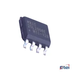
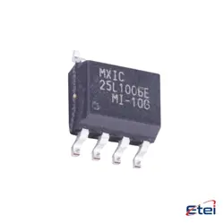
Images are for reference only
GD25WD40COIGR
+BOMIC FLASH 4MBIT SPI/DUAL 8TSSOP
-
ManufacturerGigaDevice Semiconductor (HK) Limited
-
Mfr. Part #GD25WD40COIGR
-
Datasheet GD25WD40COIGR DataSheet
-
In Stock2184
365 Days Quality Guarantee
7*24 hours service quarantee
90-day after-sales guarantee
Genuine Product Guarantee
Specifications
| Attribute | Value |
| Series | GD25WD |
| Part Status | Active |
| Memory Type | Non-Volatile |
| Memory Format | FLASH |
| Technology | FLASH - NOR (SLC) |
| Memory Size | 4Mbit |
| Memory Organization | 512K x 8 |
| Memory Interface | SPI - Dual I/O |
| Clock Frequency | 100 MHz |
| Write Cycle Time - Word, Page | 97µs, 6ms |
| Access Time | 12 ns |
| Voltage - Supply | 1.65V ~ 3.6V |
| Operating Temperature | -40°C ~ 85°C (TA) |
| Mounting Type | Surface Mount |
| Package / Case | 8-TSSOP (0.173", 4.40mm Width) |
| Supplier Device Package | 8-TSSOP |
| Base Product Number | GD25WD40 |
Overview
Description
Key features of the GD25WD40COIGR include fast read speeds, typically up to 104 MHz, and various power-saving modes that enhance its efficiency. Its architecture allows for flexible memory management, including sector and block erase capabilities. The chip is commonly used in consumer electronics, industrial applications, and automotive systems, where reliable non-volatile storage is essential.
Overall, the GD25WD40COIGR is a versatile and efficient solution for applications requiring compact and high-performance Flash memory.
Equivalent
Features
1. Capacity: 4 Mbit (512 KB).
2. Interface: SPI (Serial Peripheral Interface), enabling simple integration with microcontrollers.
3. Speed: Offers high-speed read (up to 104 MHz) and write operations, enhancing performance in data-intensive applications.
4. Voltage Range: Operates typically at 2.7V to 3.6V, making it suitable for low-power applications.
5. Endurance: Supports up to 100,000 program/erase cycles, ensuring durability for frequent data updates.
6. Data Retention: Guaranteed data retention of up to 20 years under specified conditions.
7. Packaging: Available in various packages, including SOIC and DFN, facilitating flexible design choices.
This chip is commonly used in embedded systems, automotive applications, and consumer electronics for code storage and data logging.
Pinout
Pin Count: 16 pins
Function of Pins:
1. CS (Chip Select): Activates the chip.
2. SO (Serial Output): Data output from the chip.
3. SI (Serial Input): Data input to the chip.
4. SCK (Serial Clock): Clock signal for synchronizing data transfer.
5. WP (Write Protect): Used to enable or disable write protection.
6. HOLD: Pauses the serial communication without resetting.
7. GND: Ground reference.
8. VCC: Power supply.
The remaining pins are used for various internal functions and connections. This chip supports standard SPI interface for easy integration with microcontrollers and similar devices.
Manufacturer
Application
1. Embedded Systems: For storing firmware and boot code in microcontrollers.
2. Consumer Electronics: In devices like smartphones, tablets, and wearables for data storage.
3. Automotive: In advanced driver-assistance systems (ADAS) and infotainment systems for reliable data retention.
4. Industrial Automation: For programmable logic controllers (PLCs) and machine control systems.
5. Networking Equipment: In routers and switches for firmware updates and configuration storage.
Its high endurance and reliability make it suitable for these diverse applications.