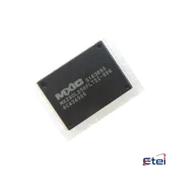
Images are for reference only
HEF4066BT
+BOMAnalog Switch ICs
-
ManufacturerNexperia
-
Mfr. Part #HEF4066BT
-
In Stock3307
365 Days Quality Guarantee
7*24 hours service quarantee
90-day after-sales guarantee
Genuine Product Guarantee
Specifications
| Attribute | Value |
Overview
Description
The HEF4066BT is a quad bilateral analog switch, part of the HEF4000B series from NXP Semiconductors. It contains four independent switches, each capable of conducting analog or digital signals. The device is designed to operate with both negative and positive voltages and is suitable for a wide range of applications such as signal gating, modulation, demodulation, and logic level conversion.
Each switch in the HEF4066BT has a control input that determines whether the switch is open or closed. When the control input is high, the switch conducts, allowing signals to pass through with minimal resistance. When the control input is low, the switch is off, effectively isolating the input from the output.
The HEF4066BT is known for its low ON resistance, fast switching times, and low power consumption, making it ideal for battery-operated devices. It is typically housed in a 14-pin dual in-line package (DIP) or small-outline integrated circuit (SOIC). The device operates over a wide voltage range, enhancing its versatility in various electronic circuits.
Each switch in the HEF4066BT has a control input that determines whether the switch is open or closed. When the control input is high, the switch conducts, allowing signals to pass through with minimal resistance. When the control input is low, the switch is off, effectively isolating the input from the output.
The HEF4066BT is known for its low ON resistance, fast switching times, and low power consumption, making it ideal for battery-operated devices. It is typically housed in a 14-pin dual in-line package (DIP) or small-outline integrated circuit (SOIC). The device operates over a wide voltage range, enhancing its versatility in various electronic circuits.
Equivalent
The HEF4066BT is a quad bilateral analog switch. Equivalent products include the CD4066 from Texas Instruments, NXP, and ON Semiconductor, the 74HC4066 from various manufacturers, and the MC14066 from ON Semiconductor. These chips perform similar functions, offering quad bilateral switching capabilities suitable for analog and digital signal applications. Always check the datasheets for specific electrical characteristics to ensure compatibility.
Features
The HEF4066BT is a quad bilateral switch IC, featuring four independently controlled analog switches. Key features include:
1. Bilateral Switching: Allows signal flow in both directions, supporting both analog and digital signals.
2. Low ON Resistance: Offers low ON resistance, ensuring minimal signal loss or distortion.
3. Wide Supply Voltage Range: Operates within a voltage range of 3V to 15V, making it versatile for different applications.
4. High Bandwidth: Capable of handling high-frequency signals, suitable for audio and RF applications.
5. Low Crosstalk: Maintains signal integrity by minimizing interference between switches.
6. High Noise Immunity: Robust against noise, ensuring reliable performance in noisy environments.
7. TTL/CMOS Compatible: Compatible with both TTL and CMOS logic families, ensuring flexible integration into various systems.
8. Low Power Consumption: Designed for efficient power usage, suitable for battery-powered applications.
9. Package Options: Available in various packages, like SOIC and DIP, to suit different design requirements.
These features make the HEF4066BT suitable for a wide array of applications, including audio routing, signal gating, and multiplexing.
1. Bilateral Switching: Allows signal flow in both directions, supporting both analog and digital signals.
2. Low ON Resistance: Offers low ON resistance, ensuring minimal signal loss or distortion.
3. Wide Supply Voltage Range: Operates within a voltage range of 3V to 15V, making it versatile for different applications.
4. High Bandwidth: Capable of handling high-frequency signals, suitable for audio and RF applications.
5. Low Crosstalk: Maintains signal integrity by minimizing interference between switches.
6. High Noise Immunity: Robust against noise, ensuring reliable performance in noisy environments.
7. TTL/CMOS Compatible: Compatible with both TTL and CMOS logic families, ensuring flexible integration into various systems.
8. Low Power Consumption: Designed for efficient power usage, suitable for battery-powered applications.
9. Package Options: Available in various packages, like SOIC and DIP, to suit different design requirements.
These features make the HEF4066BT suitable for a wide array of applications, including audio routing, signal gating, and multiplexing.
Pinout
The HEF4066BT is a quad bilateral switch IC. It has a total of 14 pins. Each switch within the IC can be controlled individually and is capable of conducting signals in both directions, allowing it to pass both analog and digital signals. Here is a brief function outline of its pin configuration:
1. Pin 1 (SW1 IN/OUT) - Input/Output for switch 1.
2. Pin 2 (SW1 OUT/IN) - Output/Input for switch 1.
3. Pin 3 (SW2 IN/OUT) - Input/Output for switch 2.
4. Pin 4 (SW2 OUT/IN) - Output/Input for switch 2.
5. Pin 5 (SW3 IN/OUT) - Input/Output for switch 3.
6. Pin 6 (SW3 OUT/IN) - Output/Input for switch 3.
7. Pin 7 (GND) - Ground.
8. Pin 8 (SW4 OUT/IN) - Output/Input for switch 4.
9. Pin 9 (SW4 IN/OUT) - Input/Output for switch 4.
10. Pin 10 (SW4 CONTROL) - Control for switch 4.
11. Pin 11 (SW3 CONTROL) - Control for switch 3.
12. Pin 12 (SW2 CONTROL) - Control for switch 2.
13. Pin 13 (SW1 CONTROL) - Control for switch 1.
14. Pin 14 (VDD) - Supply voltage.
Each switch has its own control pin, which when activated, allows the corresponding switch to conduct.
1. Pin 1 (SW1 IN/OUT) - Input/Output for switch 1.
2. Pin 2 (SW1 OUT/IN) - Output/Input for switch 1.
3. Pin 3 (SW2 IN/OUT) - Input/Output for switch 2.
4. Pin 4 (SW2 OUT/IN) - Output/Input for switch 2.
5. Pin 5 (SW3 IN/OUT) - Input/Output for switch 3.
6. Pin 6 (SW3 OUT/IN) - Output/Input for switch 3.
7. Pin 7 (GND) - Ground.
8. Pin 8 (SW4 OUT/IN) - Output/Input for switch 4.
9. Pin 9 (SW4 IN/OUT) - Input/Output for switch 4.
10. Pin 10 (SW4 CONTROL) - Control for switch 4.
11. Pin 11 (SW3 CONTROL) - Control for switch 3.
12. Pin 12 (SW2 CONTROL) - Control for switch 2.
13. Pin 13 (SW1 CONTROL) - Control for switch 1.
14. Pin 14 (VDD) - Supply voltage.
Each switch has its own control pin, which when activated, allows the corresponding switch to conduct.
Manufacturer
The HEF4066BT is manufactured by NXP Semiconductors. NXP is a global semiconductor company that provides high-performance mixed signal and standard product solutions. It focuses on several key areas such as automotive, identification, wireless infrastructure, lighting, industrial, mobile, consumer, and computing applications. NXP is known for its innovation and expertise in the semiconductor industry, offering products ranging from microcontrollers and microprocessors to integrated circuits for a variety of uses.
Application
The HEF4066BT is a quad bilateral switch IC used in various electronic applications. It serves in analog signal switching, enabling or disabling signals in audio and video equipment, instrumentation, and communication systems. It is also used in multiplexing and demultiplexing, allowing multiple signals to share a single data path. Additionally, the HEF4066BT is employed in digital logic circuits to perform routing and switching operations, in sensory circuits for signal gating, and in automation systems for controlling processes. Its versatility and bidirectional signal transmission capability make it suitable for consumer electronics, industrial control systems, and telecommunication devices.
Package
The HEF4066BT is a quad bilateral switch from NXP Semiconductors, and it typically comes in a 14-pin SO (Small Outline) package, which is suitable for surface mounting on a printed circuit board (PCB).