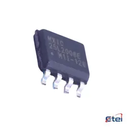
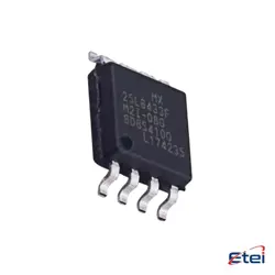
Images are for reference only
INA118P
+BOMIC INST AMP 1 CIRCUIT 8DIP
-
ManufacturerTexas Instruments
-
Mfr. Part #INA118P
-
In Stock6689
365 Days Quality Guarantee
7*24 hours service quarantee
90-day after-sales guarantee
Genuine Product Guarantee
Specifications
| Attribute | Value |
| Part Status | Last Time Buy |
| Base Product Number | INA118 |
| Amplifier Type | Instrumentation |
| Number of Circuits | 1 |
| Slew Rate | 0.9V/µs |
| Current - Input Bias | 1 nA |
| Voltage - Input Offset | 25 µV |
| Current - Supply | 350µA |
| Current - Output / Channel | 12 mA |
| Voltage - Supply Span (Min) | 2.7 V |
| Voltage - Supply Span (Max) | 36 V |
| Operating Temperature | -40°C ~ 85°C |
| Mounting Type | Through Hole |
| Package | 8-DIP (0.300", 7.62mm) |
| Supplier Device Package | 8-PDIP |
| Packaging | Tube |
| -3db Bandwidth | 800 kHz |
Overview
Description
One of the key attributes of the INA118P is its high common-mode rejection ratio (CMRR), which helps minimize noise interference, making it ideal for environments with significant electrical noise. It also offers adjustable gain settings through external resistors, allowing for customization based on specific application needs.
The INA118P is typically used in medical instrumentation, industrial process controls, and data acquisition systems. Its compact DIP-8 or SOIC-8 package enables easy integration into circuit boards, making it a go-to choice for designers looking for a reliable and efficient instrumentation amplifier.
Equivalent
Features
1. Low Input Offset Voltage: It has a very low input offset voltage, which improves measurement accuracy.
2. Low Input Bias Current: The amplifier features low input bias current, minimizing errors in applications with high source impedance.
3. High Common-Mode Rejection Ratio (CMRR): This feature allows the INA118P to effectively reject noise and interference that are common to both input lines.
4. Gain Flexibility: The gain of the amplifier can be easily set with an external resistor, allowing for flexible design adaptability.
5. Wide Supply Range: It operates over a wide power supply range, making it versatile for various applications.
6. Low Power Consumption: The INA118P is designed for low power consumption, which is beneficial for battery-powered devices.
7. Wide Temperature Range: It performs reliably over a wide temperature range, enhancing its suitability for harsh environments.
These features make the INA118P suitable for precision data acquisition systems, medical instrumentation, and industrial process controls.
Pinout
1. V- (Pin 1): Negative power supply.
2. RG (Pin 2): Gain setting resistor connection (one side).
3. +IN (Pin 3): Non-inverting input.
4. -IN (Pin 4): Inverting input.
5. REF (Pin 5): Reference voltage input.
6. RG (Pin 6): Gain setting resistor connection (other side).
7. V+ (Pin 7): Positive power supply.
8. OUT (Pin 8): Output voltage.
These pins allow the INA118P to serve as a low-power, precision instrumentation amplifier suitable for differential signal amplification.
Manufacturer
Application
1. Medical Instrumentation: For amplifying low-level biosignals such as ECG and EEG.
2. Industrial Process Control: Monitoring and controlling sensor outputs and transducers.
3. Data Acquisition Systems: Enhancing signal integrity for precise data collection.
4. Weigh Scales: Amplifying load cell or strain gauge outputs.
5. Bridge Amplifiers: Used in strain gauge and pressure sensor applications.
6. Test Equipment: For precise measurement and evaluation tasks.
7. Environmental Monitoring: Enhancing sensor signals for better measurement accuracy.
These applications benefit from the INA118P's high CMRR, low offset voltage, and low noise characteristics.
Package
Frequently Asked Questions
Q: What is the typical power supply range for the INA118P?
A: It operates from a single supply of 2.7V to 36V, or a dual supply of ±1.35V to ±18V.
Q: What is the -3dB bandwidth of this instrumentation amplifier?
A: The INA118P features a bandwidth of 800 kHz, suitable for precision signal conditioning.
Q: How low is the input bias current for high-impedance sensors?
A: The input bias current is only 1 nA, ideal for applications like bridge sensors or ECG.
Q: What is the output current drive capability per channel?
A: It can deliver up to 12 mA per channel, allowing direct drive of ADCs or low-power loads.
Q: Can this device operate in both single and dual supply configurations?
A: Yes, it supports a wide supply span from 2.7V (single) to ±18V (dual) for flexible system design.
Q: What is the slew rate and its impact on signal fidelity?
A: With a slew rate of 0.9V/μs, it ensures stable amplification for slow to moderate frequency signals.
Q: Is the INA118P suitable for precision DC measurements?
A: Yes, featuring a low input offset voltage of 25 μV and low drift, it is excellent for high-accuracy DC applications.