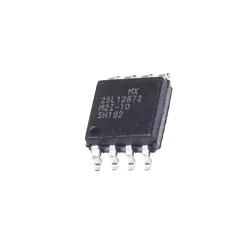
Images are for reference only
IRF7351TRPBF
+BOMMOSFET 2N-CH 60V 8A 8-SOIC
-
ManufacturerInfineon Technologies
-
Mfr. Part #IRF7351TRPBF
-
Datasheet IRF7351TRPBF DataSheet
-
Package SO8
-
In Stock1607
365 Days Quality Guarantee
7*24 hours service quarantee
90-day after-sales guarantee
Genuine Product Guarantee
Specifications
| Attribute | Value |
| Package | Tape & Reel (TR),Cut Tape (CT) |
| Series | HEXFET® |
| ProductStatus | Active |
| FETType | 2 N-Channel (Dual) |
| FETFeature | Logic Level Gate |
| DraintoSourceVoltage(Vdss) | 60V |
| Current-ContinuousDrain(Id)@25°C | 8A |
| RdsOn(Max)@IdVgs | 17.8mOhm @ 8A, 10V |
| Vgs(th)(Max)@Id | 4V @ 50µA |
| GateCharge(Qg)(Max)@Vgs | 36nC @ 10V |
| InputCapacitance(Ciss)(Max)@Vds | 1330pF @ 30V |
| Power-Max | 2W |
| OperatingTemperature | -55°C ~ 150°C (TJ) |
| MountingType | Surface Mount |
| Package/Case | 8-SOIC (0.154, 3.90mm Width) |
Overview
Description
Key specifications of the IRF7351TRPBF include a low on-resistance, which minimizes power loss and heat generation, and a high threshold voltage, ensuring that it operates effectively under various load conditions. It is housed in a surface-mount SO-8 package, making it suitable for automated assembly and integration into small form-factor designs. The device is optimized for fast switching and offers reliable performance across a broad range of temperatures.
Overall, the IRF7351TRPBF is valued for its efficiency, compactness, and reliability in power switching applications.
Equivalent
1. NXP PSMN1R2-25YLC
2. Vishay Si4936DY
3. ON Semiconductor NTMFS4935NT1G
4. Infineon BSC026N04LS
These alternatives may vary in specific electrical characteristics and package types, so it's important to verify compatibility with your application. Always consult datasheets for detailed specifications.
Features
1. Voltage and Current Ratings: It has a maximum drain-to-source voltage (V_DS) of 30V and a continuous drain current (I_D) of up to 7.5A.
2. Low On-Resistance: The device offers a low on-resistance (R_DS(on)) of approximately 0.022 ohms, enhancing performance by reducing power loss.
3. Gate Threshold Voltage: The gate threshold voltage (V_GS(th)) ranges from 1.0V to 2.5V, facilitating easy driving with lower voltages.
4. Package Type: It is housed in a compact SO-8 package, ideal for space-constrained applications.
5. Thermal Performance: It provides good thermal performance owing to its efficient package design that supports better heat dissipation.
6. Applications: Commonly used in DC-DC converters, load switches, and power management for portable and battery-powered devices.
These features make it suitable for high-efficiency and compact-sized electronic applications.
Pinout
1. Pin 1 & 8 (Drain1 & Drain2): These are connected to the drains of the MOSFETs. They are used for the main current flow from drain to source when the MOSFETs are activated.
2. Pin 2 & 7 (Gate1 & Gate2): These pins control the gates of the two MOSFETs. Applying a voltage here turns the MOSFETs on or off.
3. Pin 3 & 6 (Source1 & Source2): These are the sources of the MOSFETs. Current flows from these pins to the corresponding drain pins when the MOSFETs are on.
4. Pin 4 & 5 (Substrate or Common Source): These are typically connected internally and serve as a common source or substrate connection for both transistors.
This MOSFET is commonly used in power management applications, DC-DC converters, and loads requiring efficient switching.