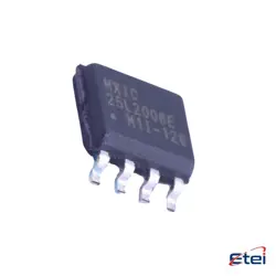
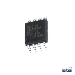
Images are for reference only
LTC1871IMS
+BOMSwitching Controllers LTC1871 - Wide Input Range, No RSENSE Current Mode Boost, Flyback and SEPIC Controller
-
ManufacturerAnalog Devices
-
Mfr. Part #LTC1871IMS
-
Datasheet LTC1871IMS DataSheet
-
In Stock16179
365 Days Quality Guarantee
7*24 hours service quarantee
90-day after-sales guarantee
Genuine Product Guarantee
Specifications
| Attribute | Value |
Overview
Description
Equivalent
1. TI TPS40210: A wide-input voltage boost controller.
2. Maxim Integrated MAX668: A boost controller with similar features.
3. ON Semiconductor NCP1406: Another boost controller with comparable capabilities.
When selecting a replacement, ensure that the electrical specifications and features match your requirements for the application. Always consult the datasheets for detailed information to ensure compatibility.
Features
1. Wide Input Voltage Range: It supports a broad input voltage range, typically from 2.5V to 36V, which is adaptable for various power sources.
2. Output Voltage Flexibility: The device allows for adjustable output voltages, enabling customization according to specific application needs.
3. High Efficiency: Designed to provide high efficiency over a wide load range, thus reducing power losses and thermal management concerns.
4. Current Mode Control: Implements current mode control for fast transient response and simple loop compensation.
5. Low Shutdown Current: Features a low shutdown current, minimizing power consumption when the device is not active.
6. Programmable Frequency: Offers a programmable switching frequency, allowing designers to optimize for efficiency or component size.
7. Protection Features: Includes features like overvoltage protection, overcurrent protection, and thermal shutdown to ensure reliability and safety.
These features make the LTC1871IMS suitable for applications like portable devices, automotive systems, and industrial equipment.
Pinout
Here's a brief overview of its pin count and functions:
1. VCC (Pin 1) - Power supply for the chip.
2. SENSE (Pin 2) - Current sense input.
3. ITH/RUN (Pin 3) - Error amplifier compensation point and run control input.
4. SGND (Pin 4) - Small-signal ground reference.
5. VFB (Pin 5) - Feedback voltage input for output voltage regulation.
6. NC (Pin 6) - No connection.
7. SYNC (Pin 7) - Frequency sync input.
8. RT (Pin 8) - Timing resistor to set the switching frequency.
9. BOOST (Pin 9) - Supply for the N-channel MOSFET gate driver.
10. TG (Pin 10) - Gate driver output for the external N-channel MOSFET.
These pins collectively allow the LTC1871IMS to regulate the output voltage effectively by controlling an external switch, making it suitable for a variety of power supply applications.
Manufacturer
Application
1. Telecommunications: Powering network equipment and infrastructure.
2. Automotive: Supplying power to electronic systems within vehicles.
3. Industrial Power Systems: Used in industrial automation and control systems.
4. Battery-Powered Devices: Extending battery life in portable electronics.
5. Solar Power Systems: Enhancing energy conversion in solar chargers and inverters.
6. Consumer Electronics: Providing stable power to devices such as laptops and gaming consoles.
Its ability to operate in boost, flyback, and SEPIC configurations makes it adaptable for various power supply needs.