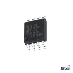
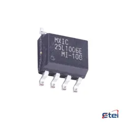
Images are for reference only
NCP1252BDR2G
+BOMIC OFFLINE SWITCH MULT TOP 8SOIC
-
Manufactureronsemi
-
Mfr. Part #NCP1252BDR2G
-
In Stock3434
365 Days Quality Guarantee
7*24 hours service quarantee
90-day after-sales guarantee
Genuine Product Guarantee
Specifications
| Attribute | Value |
| PartStatus | Active |
| BaseProductNumber | NCP1252 |
| OutputIsolation | Isolated |
| InternalSwitch(s) | No |
| Topology | Flyback, Forward |
| Voltage-StartUp | 10 V |
| Voltage-Supply(Vcc/Vdd) | 9V ~ 28V |
| DutyCycle | 80% |
| Frequency-Switching | Up to 500kHz |
| FaultProtection | Current Limiting |
| ControlFeatures | Frequency Control, Soft Start |
| OperatingTemperature | -25°C ~ 125°C (TJ) |
| Package | 8-SOIC (0.154", 3.90mm Width) |
| SupplierDevicePackage | 8-SOIC |
| MountingType | Surface Mount |
| Packaging | Cut Tape (CT), Tape & Reel (TR) |
Overview
Description
The NCP1252BDR2G is a PWM current-mode controller designed for flyback power supplies. It is suitable for applications requiring high efficiency and low standby power, such as adapters and chargers. The device features a wide operating frequency range and a built-in frequency jittering function to reduce electromagnetic interference (EMI).
Key features include:
- Current-mode control for improved transient response and simplified loop compensation.
- Frequency jittering for reduced EMI.
- Skip-cycle operation for improved efficiency at light loads.
- Internal ramp compensation to enhance stability.
- Built-in soft-start to prevent output voltage overshoot.
- Adjustable output over-voltage protection and overload protection.
- Latched or auto-recovery protection mode options.
The NCP1252BDR2G operates over a wide input voltage range and supports applications up to 100 watts. It comes in a compact SOIC-8 package, making it suitable for space-constrained designs. This controller is often chosen for its robustness and efficiency in consumer electronics, computing, and industrial applications.
Key features include:
- Current-mode control for improved transient response and simplified loop compensation.
- Frequency jittering for reduced EMI.
- Skip-cycle operation for improved efficiency at light loads.
- Internal ramp compensation to enhance stability.
- Built-in soft-start to prevent output voltage overshoot.
- Adjustable output over-voltage protection and overload protection.
- Latched or auto-recovery protection mode options.
The NCP1252BDR2G operates over a wide input voltage range and supports applications up to 100 watts. It comes in a compact SOIC-8 package, making it suitable for space-constrained designs. This controller is often chosen for its robustness and efficiency in consumer electronics, computing, and industrial applications.
Equivalent
The NCP1252BDR2G is a PWM controller used in power supply applications. Equivalent or similar products can include:
1. Texas Instruments UC3842/UC3843: Widely used PWM controllers with similar functionality.
2. ON Semiconductor NCP1250: Offers similar features with some variations in specifications.
3. STMicroelectronics UC3842B: Another PWM controller with comparable features.
Ensure to check the datasheets for detailed specifications and compatibility with your application.
1. Texas Instruments UC3842/UC3843: Widely used PWM controllers with similar functionality.
2. ON Semiconductor NCP1250: Offers similar features with some variations in specifications.
3. STMicroelectronics UC3842B: Another PWM controller with comparable features.
Ensure to check the datasheets for detailed specifications and compatibility with your application.
Features
The NCP1252BDR2G is a current-mode PWM controller designed for power supplies. It features a wide operating voltage range from 8 V to 28 V and offers high efficiency across load conditions. The device incorporates a frequency jittering function to minimize EMI. It supports multiple protection mechanisms, including overvoltage, overcurrent, and thermal shutdown. The NCP1252BDR2G also provides a low standby power consumption mode, making it suitable for energy-efficient designs. Its integrated high-voltage startup circuit ensures rapid power-up, and its cycle-by-cycle current limiting enhances safety. Additionally, the controller supports frequency foldback to improve performance under light-load conditions. This combination of features makes it ideal for use in applications such as adapters, TVs, and other consumer electronics.
Pinout
The NCP1252BDR2G is a PWM current-mode controller designed for flyback power supply applications. It typically comes in an 8-pin package. Here is a concise description of its pin functions:
1. VCC (Pin 1): Power supply input for the controller.
2. FB (Pin 2): Feedback input; used to regulate output by comparing the voltage to a reference.
3. CS (Pin 3): Current sense input; monitors the current through the power switch.
4. GND (Pin 4): Ground reference for the IC.
5. DRV (Pin 5): Drive output; delivers the control signal to the gate of the power MOSFET.
6. NC (Pin 6): No connect; not internally connected.
7. NC (Pin 7): No connect; not internally connected.
8. VDD (Pin 8): Auxiliary supply input; powers the IC during startup and normal operation.
This configuration allows for efficient control of power conversion in flyback converters, incorporating features like low standby power, high-voltage startup, and cycle-by-cycle current limiting.
1. VCC (Pin 1): Power supply input for the controller.
2. FB (Pin 2): Feedback input; used to regulate output by comparing the voltage to a reference.
3. CS (Pin 3): Current sense input; monitors the current through the power switch.
4. GND (Pin 4): Ground reference for the IC.
5. DRV (Pin 5): Drive output; delivers the control signal to the gate of the power MOSFET.
6. NC (Pin 6): No connect; not internally connected.
7. NC (Pin 7): No connect; not internally connected.
8. VDD (Pin 8): Auxiliary supply input; powers the IC during startup and normal operation.
This configuration allows for efficient control of power conversion in flyback converters, incorporating features like low standby power, high-voltage startup, and cycle-by-cycle current limiting.
Manufacturer
The NCP1252BDR2G is manufactured by ON Semiconductor, now known as onsemi. Onsemi is a semiconductor manufacturing company that specializes in intelligent power and sensing technologies. It provides a wide range of products, including power management, analog, sensors, logic, timing, connectivity, discrete, and custom devices. The company serves various markets such as automotive, industrial, computing, communications, and consumer electronics. Onsemi is known for its focus on energy-efficient solutions and plays a significant role in enabling technology for electric vehicles, smart buildings, and industrial automation.
Application
The NCP1252BDR2G is a PWM controller primarily used in power supply applications. It is designed for use in isolated and non-isolated flyback converters. Key application areas include:
1. AC-DC Adapters: Suitable for power adapters for laptops, tablets, and other electronic devices.
2. Power Supplies: Used in standby and auxiliary power supplies for TVs, monitors, and other consumer electronics.
3. LED Drivers: Used in LED driver circuits for efficient power management.
4. Battery Chargers: Useful in chargers for various batteries, providing controlled power delivery.
5. Industrial Power Supplies: Applicable in industrial settings where efficient power conversion is needed.
Its features like frequency jittering, skip cycle, and adjustable Over Power Protection (OPP) make it versatile for these applications.
1. AC-DC Adapters: Suitable for power adapters for laptops, tablets, and other electronic devices.
2. Power Supplies: Used in standby and auxiliary power supplies for TVs, monitors, and other consumer electronics.
3. LED Drivers: Used in LED driver circuits for efficient power management.
4. Battery Chargers: Useful in chargers for various batteries, providing controlled power delivery.
5. Industrial Power Supplies: Applicable in industrial settings where efficient power conversion is needed.
Its features like frequency jittering, skip cycle, and adjustable Over Power Protection (OPP) make it versatile for these applications.
Package
The NCP1252BDR2G is typically available in an SOIC-8 package, which is a Small Outline Integrated Circuit with 8 pins. This package type is commonly used for surface-mount applications, providing a compact and reliable form factor for electronic components.