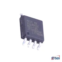
Images are for reference only
TOP271KG
+BOMIC OFFLINE SWITCH FLYBACK 12ESOP
-
ManufacturerPower Integrations
-
Mfr. Part #TOP271KG
-
Datasheet TOP271KG DataSheet
-
Package BESOP-12
-
In Stock1729
365 Days Quality Guarantee
7*24 hours service quarantee
90-day after-sales guarantee
Genuine Product Guarantee
Specifications
| Attribute | Value |
| Package | Tube |
| Series | TOPSwitch®-JX |
| ProductStatus | Discontinued at Digi-Key |
| OutputIsolation | Isolated |
| InternalSwitch(s) | Yes |
| Voltage-Breakdown | 725V |
| Topology | Flyback |
| DutyCycle | 78% |
| Frequency-Switching | 66kHz, 132kHz |
| Power(Watts) | 102 W |
| FaultProtection | Current Limiting, Over Load, Over Temperature, Over Voltage, Short Circuit |
| ControlFeatures | Frequency Control |
| OperatingTemperature | -40°C ~ 150°C (TJ) |
| Package/Case | 12-BESOP (0.350, 8.89mm Width), 11 Leads, Exposed Pad |
| SupplierDevicePackage | 12-ESOP |
Overview
Description
Equivalent
1. NCP107x Series by ON Semiconductor
2. LNK6x Series by Power Integrations
3. VIPer* Series by STMicroelectronics
Ensure the selected equivalent meets your design's specific requirements such as input voltage range, output power, and efficiency.
Features
1. High Efficiency: Designed to maximize energy efficiency, reducing power losses.
2. Compact Design: Integrates multiple functions in a single chip, saving space in electronic designs.
3. Wide Input Voltage Range: Can handle varying input voltages, making it suitable for different power conditions.
4. Precise Regulation: Provides accurate output voltage and current regulation.
5. Protection Features: Includes over-voltage, over-current, and thermal shutdown protections to enhance reliability and safety.
6. Low Standby Power: Minimizes power consumption during idle or low-load conditions.
7. Ease of Use: Simplifies the design process with fewer external components required.
8. Flexibility: Adaptable to various power supply designs and applications.
These features make the TOP271KG suitable for applications in consumer electronics, industrial devices, and other areas requiring efficient power management.
Pinout
The pins and their functions are typically as follows:
1. SOURCE (S) - Pin 1: This is the power switch source and primary circuit common.
2. CONTROL (C) - Pin 2: This pin is used for the control circuit and feedback. It is where the IC receives its supply current.
3. SYNCHRONOUS RECTIFIER (SR) - Pin 3: Provides a drive signal for synchronous rectification.
4. MULTI-FUNCTION (M) - Pin 4: Can be used for line-sense, under-voltage, and over-voltage protections.
5. BYPASS/MULTI-FUNCTION (BP/M) - Pin 5: Used for setting the current limit and frequency.
6. DRAIN (D) - Pin 6: The power MOSFET drain connection. It is the output switch's drain.
7. DRAIN (D) - Pin 7: Also a drain pin, often internally connected to Pin 6 for heat dissipation.
Please refer to the datasheet for detailed specifications and application guidelines.
Manufacturer
Application
1. Consumer Electronics: Used in adapters and chargers for devices like smartphones, tablets, and laptops.
2. Industrial Power Supplies: Powers and regulates equipment in industrial settings, ensuring efficiency and reliability.
3. LED Lighting: Drives and manages power for LED lighting systems, enhancing energy efficiency.
4. Home Appliances: Integrated into appliances for efficient power management, reducing energy consumption.
5. Smart Meters: Used in smart metering solutions for accurate and efficient energy distribution.
Overall, it enhances energy efficiency, reduces component count, and supports compact design in various electronic applications.