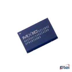
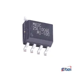
Images are for reference only
UPC8179TK-A
+BOMIC RF AMP GP 2.4GHZ 6-MINIMOLD
-
ManufacturerCEL
-
Mfr. Part #UPC8179TK-A
-
Package 6-SMD, Flat Leads
-
In Stock2967
365 Days Quality Guarantee
7*24 hours service quarantee
90-day after-sales guarantee
Genuine Product Guarantee
Specifications
| Attribute | Value |
| Supplier | CEL |
| Package / Case | Bulk |
| Part Status | Obsolete |
| Frequency | 100MHz ~ 2.4GHz |
| P1d B | -2dBm ~ 0.5dBm |
| Gain | 13dB ~ 17.5dB |
| Noise Figure | 5dB ~ 6.5dB |
| RF Type | General Purpose |
| Voltage - Supply | 2.4V ~ 3.3V |
| Supply Current | 2.6mA ~ 5.4mA |
| Test Frequency | 1.9GHz |
| Mounting Type | Surface Mount |
Overview
Description
Equivalent
1. Mini-Circuits PGA-103+
2. Qorvo TQP3M9009
3. Analog Devices HMC754LC3C
4. NXP BGU7004
These alternatives offer similar gain, frequency range, and noise figures. Always check the datasheets for compatibility and specific parameters to ensure they meet your design requirements.
Features
1. Frequency Range: Operates effectively across a wide frequency range, making it suitable for various RF applications.
2. Low Noise Figure: Offers a low noise figure, enhancing signal quality by reducing the noise level in the amplification process.
3. High Gain: Provides high gain to amplify weak signals efficiently, essential for long-range communication applications.
4. Compact Package: Comes in a small, surface-mount package, suitable for compact and lightweight designs.
5. Low Power Consumption: Designed for efficient power usage, making it ideal for battery-operated devices.
6. Wide Supply Voltage Range: Compatible with a broad range of supply voltages, offering design flexibility.
7. High Linearity: Ensures minimal distortion, crucial for maintaining signal integrity in demanding applications.
These features make the UPC8179TK-A a versatile choice for improving signal reception in wireless communication systems, including mobile phones, Wi-Fi devices, and other RF communication equipment.
Pinout
The UPC8179TK-A commonly has a pin count of around 6 pins. The key functions of these pins include:
1. RF Input (Pin 1): Receives the radio frequency signal to be amplified.
2. Ground (Pin 2): Provides a common reference point for the circuit.
3. Vcc (Pin 3): Supplies the necessary operating voltage to the IC.
4. RF Output (Pin 4): Outputs the amplified RF signal.
5. Bypass/NC (Pin 5): May be used for bypassing or left unconnected depending on specific design requirements.
6. Bias (Pin 6): Sets the operating point for the amplifier to ensure proper functioning.
Always refer to the specific datasheet of the manufacturer for precise details as variations can occur in different versions or revisions of the IC.
Manufacturer
Application
1. Wireless Communication Systems: Enhances signal reception in mobile phones, tablets, and wireless routers.
2. Satellite Communication: Improves signal quality and sensitivity in satellite receivers.
3. GPS Devices: Boosts weak signals for better accuracy and reliability.
4. RFID Systems: Amplifies signals for better tag reading performance.
5. Broadcasting Equipment: Used in TV tuners and radio receivers to improve signal clarity.
6. IoT Devices: Enhances connectivity by improving signal strength in various IoT applications.
Its low noise figure and high gain make it ideal for these applications, where signal integrity is crucial.