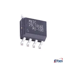
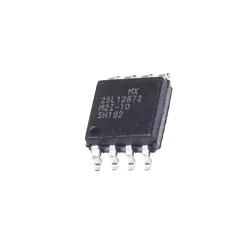
Images are for reference only
HEF4013BT
+BOMFlip Flops
-
ManufacturerNexperia
-
Mfr. Part #HEF4013BT
-
In Stock23001
365 Days Quality Guarantee
7*24 hours service quarantee
90-day after-sales guarantee
Genuine Product Guarantee
Specifications
| Attribute | Value |
Overview
Description
HEF4013BT is a course typically offered in higher education institutions, though specific details can vary depending on the institution. Generally, it could be part of a curriculum in fields like engineering, business, technology, or finance. The course might cover advanced topics relevant to its field, integrating theoretical knowledge with practical applications.
Students enrolling in HEF4013BT can expect to engage with complex subject matter, participate in hands-on projects, and develop critical analytical skills. Coursework may include lectures, seminars, group discussions, and lab work or case studies, aimed at enhancing understanding and problem-solving abilities.
Assessment methods might involve a combination of exams, project work, and presentations, encouraging students to demonstrate both individual understanding and collaborative capabilities. Prerequisites for this course may include completion of foundational courses or relevant experience, ensuring students have the necessary background knowledge.
For specific details about HEF4013BT, including its focus, prerequisites, and structure, refer to the course syllabus or consult the academic institution offering the course.
Students enrolling in HEF4013BT can expect to engage with complex subject matter, participate in hands-on projects, and develop critical analytical skills. Coursework may include lectures, seminars, group discussions, and lab work or case studies, aimed at enhancing understanding and problem-solving abilities.
Assessment methods might involve a combination of exams, project work, and presentations, encouraging students to demonstrate both individual understanding and collaborative capabilities. Prerequisites for this course may include completion of foundational courses or relevant experience, ensuring students have the necessary background knowledge.
For specific details about HEF4013BT, including its focus, prerequisites, and structure, refer to the course syllabus or consult the academic institution offering the course.
Equivalent
The HEF4013BT is a dual D-type flip-flop IC. Equivalent products include the CD4013 series from various manufacturers such as Texas Instruments (CD4013B), Nexperia, and ON Semiconductor. These alternatives offer similar functionality and are often pin-compatible, making them suitable substitutes for use in digital circuits requiring D-type flip-flops. Always check the datasheet for exact specifications to ensure compatibility in your specific application.
Features
The HEF4013BT is a dual D-type flip-flop integrated circuit manufactured by Nexperia. Each flip-flop within the IC has two data inputs (D), a clock input (CP), a set input (SD), a reset input (RD), and complementary outputs (Q and Q̅). Some key features include:
1. Dual Independent Flip-Flops: The IC contains two separate flip-flops, allowing for independent operation.
2. Data Storage and Transfer: The D-type design enables data storage and transfer on the rising edge of the clock pulse.
3. Set and Reset Functions: The flip-flops can be asynchronously set or reset using the SD and RD inputs, respectively.
4. High Noise Immunity: It is designed for high signal integrity and noise immunity.
5. Low Power Consumption: Suitable for battery-powered applications due to its low power requirements.
6. Wide Operating Voltage: Operates over a wide voltage range, typically from 3V to 15V.
7. Standardized Output Levels: Compatible with other logic families, making it versatile in mixed-signal circuits.
These characteristics make the HEF4013BT suitable for applications requiring data latching, counters, and shift registers.
1. Dual Independent Flip-Flops: The IC contains two separate flip-flops, allowing for independent operation.
2. Data Storage and Transfer: The D-type design enables data storage and transfer on the rising edge of the clock pulse.
3. Set and Reset Functions: The flip-flops can be asynchronously set or reset using the SD and RD inputs, respectively.
4. High Noise Immunity: It is designed for high signal integrity and noise immunity.
5. Low Power Consumption: Suitable for battery-powered applications due to its low power requirements.
6. Wide Operating Voltage: Operates over a wide voltage range, typically from 3V to 15V.
7. Standardized Output Levels: Compatible with other logic families, making it versatile in mixed-signal circuits.
These characteristics make the HEF4013BT suitable for applications requiring data latching, counters, and shift registers.
Pinout
The HEF4013BT is a Dual D-type flip-flop IC with set and reset features. It consists of two identical, independent data-type flip-flops. Each flip-flop has independent data, set, reset, and clock inputs, along with complementary outputs (Q and Q̅).
The IC is typically housed in a 14-pin package. Here is a concise description of the pin functions:
1. VSS (Pin 7): Ground supply voltage.
2. VDD (Pin 14): Positive supply voltage.
3. D1 (Pin 5) and D2 (Pin 9): Data inputs for flip-flop 1 and flip-flop 2, respectively.
4. CP1 (Pin 3) and CP2 (Pin 11): Clock inputs for flip-flop 1 and flip-flop 2, respectively.
5. SD1 (Pin 6) and SD2 (Pin 8): Set inputs for flip-flop 1 and flip-flop 2, respectively.
6. RD1 (Pin 4) and RD2 (Pin 10): Reset inputs for flip-flop 1 and flip-flop 2, respectively.
7. Q1 (Pin 1) and Q2 (Pin 13): Normal outputs for flip-flop 1 and flip-flop 2, respectively.
8. Q̅1 (Pin 2) and Q̅2 (Pin 12): Complementary outputs for flip-flop 1 and flip-flop 2, respectively.
This IC is used in applications requiring flip-flop operations like data storage, data transfer, and simple binary counting.
The IC is typically housed in a 14-pin package. Here is a concise description of the pin functions:
1. VSS (Pin 7): Ground supply voltage.
2. VDD (Pin 14): Positive supply voltage.
3. D1 (Pin 5) and D2 (Pin 9): Data inputs for flip-flop 1 and flip-flop 2, respectively.
4. CP1 (Pin 3) and CP2 (Pin 11): Clock inputs for flip-flop 1 and flip-flop 2, respectively.
5. SD1 (Pin 6) and SD2 (Pin 8): Set inputs for flip-flop 1 and flip-flop 2, respectively.
6. RD1 (Pin 4) and RD2 (Pin 10): Reset inputs for flip-flop 1 and flip-flop 2, respectively.
7. Q1 (Pin 1) and Q2 (Pin 13): Normal outputs for flip-flop 1 and flip-flop 2, respectively.
8. Q̅1 (Pin 2) and Q̅2 (Pin 12): Complementary outputs for flip-flop 1 and flip-flop 2, respectively.
This IC is used in applications requiring flip-flop operations like data storage, data transfer, and simple binary counting.
Manufacturer
The HEF4013BT is manufactured by Nexperia. Nexperia is a semiconductor company that specializes in producing discrete, logic, and MOSFET devices. It was originally part of NXP Semiconductors but became an independent company in 2017. Nexperia focuses on efficiency, producing components that are essential for the electronics industry, including automotive, industrial, computing, and consumer electronics sectors. The company is known for its high-volume production capabilities and commitment to sustainable practices.
Application
The HEF4013BT is a dual D-type flip-flop IC used in various digital applications. It is commonly employed in data storage, data transfer, and data synchronization tasks. Specific application areas include digital counters, registers, frequency dividers, and shift registers. Additionally, it is used in timing applications and as a basic memory element in digital circuits. The device can be found in consumer electronics, communication systems, and instrumentation due to its reliability and ability to operate over a wide range of voltages and temperatures. Its versatility makes it suitable for both educational purposes in digital electronics courses and practical applications in designing digital logic systems.
Package
The HEF4013BT is a dual D-type flip-flop integrated circuit. It is typically packaged in a small outline integrated circuit (SOIC) package for surface-mount technology (SMT), specifically a SO16 package, which means it has 16 pins.